 SAFE & SECURE
 Frequently Asked Questions
Home / Faq
-
1. Typical 3-Phase Wiring Diagrams and Equations for Resistive Heaters
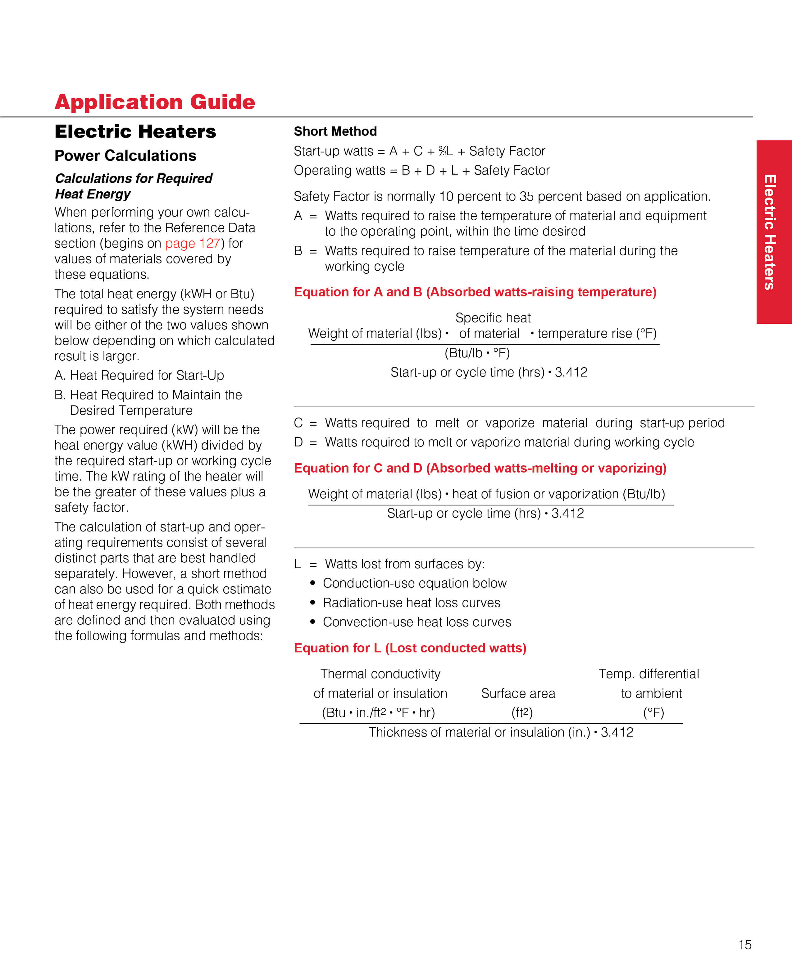
Definitions
For Both Wye and Delta (Balanced Loads) Wye and Delta Equivalent VP= Phase Voltage
VL= Line Voltage
IP= Phase Current
IL= Line Current
R = R1 = R2 = R3 = Resistance of each branch
W = WattageWDELTA= 3 WWYE
WODELTA= ¾ WDELTA
WOWYE= ½ WWYE
Equations
Phase Wye (Balanced Load) Phase Open Wye (No Neutral) 
Phase Delta (Balanced Load) 3-Phase Open Delta 
-
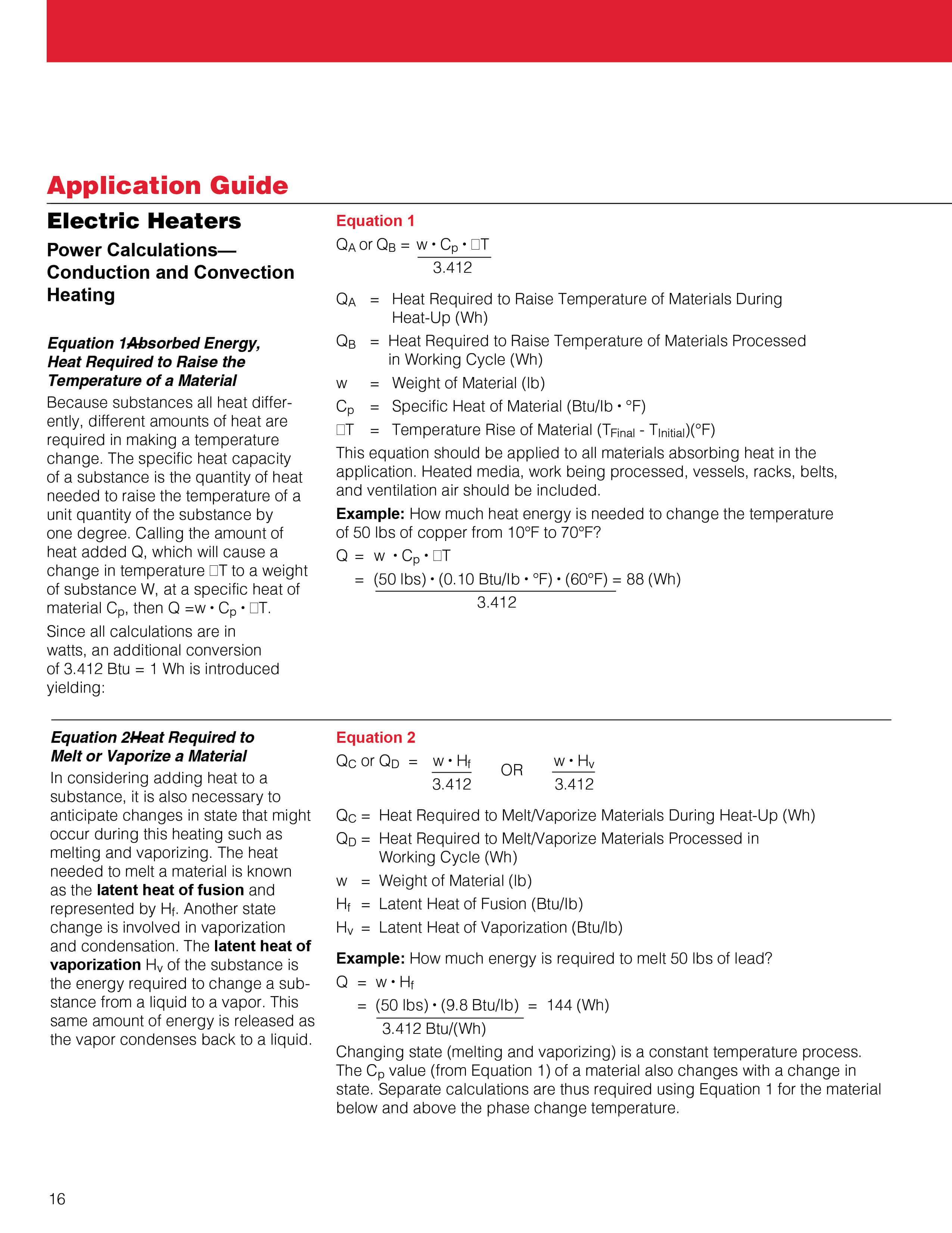
2.OHMS LAW
-
3. TEMPERATURE CONVERSION FORMULAES
To Convert To… Multiply… By… Atmospheres -- (atm) Bar -- Inches Mercury (in Hg) Pounds/square inch (psi) Torr -- 0.9869
0.03342
0.06805
0.001316
Bar Atmospheres (atm) Pounds/square inch (psi) 1.0133
0.06895British Thermal Units (Btu) Joules (J)
Kilowatt-hours (KWh)
Watt-hours (Wh)
0.000948
3412
3.412
British Thermal Units/hour (Btu/h) Kilocalories/hour (kcal/h)
Watts (W)
3.969
3.412
British Thermal Units/inches
hour-square foot---°F
British Thermal Units/pound
British Thermal
Units/pound---°F
(Btu---in)
(h-ft2---°F)
(Btu/lb)
(Btu/lb---°F)
Watts/meter---°C (W/m---°C)
Kilojoules/kilogram (kJ/kg)
Kilojoules/kilogram---°C (kJ/kg---°C)
6.933
0.4299
0.2388
Calories (cal) Joules (J) 0.2388 Centimeters (cm) Feet (ft)
Inches (in)
30.48
2.54
Centimeters/second (cm/s) Feet/minute (fpm) 0.508 Cubic centimeters (cm3or cc) Cubic feet (ft3)
Cubic inches (in3)
Milli Liters (ml)
28,320
16.39
1.0
Cubic feet (ft3) Cubic meters (m3)
Gallons, U.S. (gal)
Liters (l)
35.32
0.1337
.03532
Cubic inches (in3) Cubic centimeters (cm3or cc) 0.061 Cubic meters (m3) Gallons, U.S. (gal)
Liters (l)
Cubic feet (ft3)
0.003785
0.001
0.02832
Cubic meters/hour (m3/h) Cubic feet/minute (cfm)
Gallons/minute (gpm)
1.699
0.2271
Cubic meters/second (m3/s) Cubic feet/minute (cfm) 0.000472 Feet (ft) Centimeters (cm)
Meters (m)
0.03281
3.281
Feet/minute (fpm) Centimeters/second (cm/s)
Meters/second (m/s)1.969
196.9Gallons, Imperial -- Gallons, U.S. (gal) 0.8327 Gallons, U.S. (gal) Cubic feet (ft3)
Cubic meters (m3)
Gallons, Imperial --
Liters (l)
7.481
264.2
1.201
0.2642
Gallons/minute (gpm) Cubic meters/hour
Liters/second (m3/h)
(l/s)
4.403
15.85
Grams (g) Ounces (oz)
Pounds (lb)
28.35
453.6
Grams/cubic centimeter (g/cm3) Kilograms/cubic meter (kg/m3)
Pounds/cubic foot (lb/ft3)
Pounds/cubic inch (lb/in3)
0.001
0.01602
27.68
Inches (in) Centimeters (cm)
Millimeters (mm)
0.3937
0.03937
Joules (J) British Thermal Units (Btu)
Calories (cal)
Watt-hours (Wh)
1055
4.187
3600
Joules/second (J/s) British Thermal Units/hour (Btu/h)
Watts (W)
0.2931
1Kilocalories/hour (kcal/h) Btu/hour
(Btu/h)
Btu/hour (Btu/h)
0.252Kilograms
Kilograms/cubic meter
Kilograms/cubic meter
Kilograms/square
centimeter(kg)
(kg/m3)
(kg/m3)
(kg/cm2)
Pounds (lb)
Grams/cubic centimeter (g/cm3)
Pounds/cubic foot (lb/ft3)
Pounds/square inch (psi)
0.4536
1000
16.02
0.07031Kilojoules
Kilojoules/kilogram
Kilojoules/kilogram---ºC
(kJ)
(kJ/kg)
(kJ/kg---ºC)
Watt-hours (Wh)
British Thermal Units/pound(Btu/lb)
British Thermal
Units/pound---ºF (Btu/lb---ºF)
3.6
2.326
4.187Kilometers/hour
(kJ)
(kJ/kg)
(kJ/kg---ºC)
Miles/hour (mph)
1.609
Kilopascals
(kPa)
Pounds/square inch (psi)
6.895
Kilowatts
(KW)
British Thermal Units/hour (Btu/h)
Watts (W)
0.0002931 0.001
Kilowatt-hours
(KWh)
British Thermal Units Btu)
Watt-hours (Wh)
0.0002931
0.001
Liters
(l)
Cubic Feet (ft3)
Cubic Meters (m3)
Gallons, U.S. (gal)
28.32
1000
3.785
Liters/second
(l/s)
Cubic feet/minute (cfm)
Gallons/minute (gpm)
0.4719
0.06309
Meters
Meters/second(m)
(m/s)Feet (ft)
Feet/minute (fpm)
0.3048
0.00508
(mph) Kilometers/hour (km/h)
0.6215
Miles/hour (mph) KKilometers/hour (km/h)
0.6215
Millimeters (mm) Inches (in)
25.4
Newtons/square meter (N/m2) Pounds/square inch (psi)
6,895
Ounces (oz) Grams (g)
0.035274 Pounds (lb) Grams (g)
Kilograms (kg)
0.002205
2.205Pounds/cubic foot (lb/ft3) Grams/cubic centimeter (g/cm3)
Kilograms/cubic meter (kg/m3)
62.43
0.06243Pounds/cubic inch (lb/in3) Grams/cubic centimeter (g/cm3)
0.03613 Pounds/square inch (psi) Bar - Kilograms/square centimeter (kg/cm2)
Kilopascals (kPa)
Newtons/square meter (N/m2)
14.504
14.22
0.145
0.000145Square centimeters (cm2) Square feet (ft2)
Square inches (in2)
929
6.452Square feet (ft2) Square centimeters (cm2)
Square meters (m2)
0.001076
10.76Square inches (in2) Square centimeters (cm2)
0.155
Square meters (m2) Square feet (ft2)
0.0929
Torr Inches Mercury (in. Hg)
Pounds/square inch (psi)0.03937
51.710.Watts
Watts Watts (W) British Thermal Units/hour (Btu/h)
Joules/second (J/s)0.2931 1
Watt-hours (Wh) British Thermal Units (Btu)
Joules (J)
Kilojoules (kJ)0.2931
0.0002778
0.2778Watts/meter---ºC
Watts/square centimeter
Watts/square inch(W/m---ºC)
(W/cm2)
(W/in2)Watts/square inch (W/in2)
Watts/square centimeter (W/cm2)0.1442
0.155
6.452Watts/meter---ºC
Watts/square centimeter
Watts/square inch(W/m---ºC)
(W/cm2)
(W/in2)Watts/square inch (W/in2)
Watts/square centimeter (W/cm2)0.1442
0.155
6.452Temperature Scale Convert to by… Fahrenheit °F = 1.8°C + 32° Celsius °C =5/9(°F-32°) Rankine °R = 1.8K + 0.6°
°R = °F + 460°Kelvin K =5/9(°R-0.6°)
K = °C + 273° -
4. Temperature Sensor Attributes
Criteria Thermocouple RTD Thermistor Temperature Range Very wide -450°F +4200°F Wide -400°F +1200°F Narrow -100°F +500°F Interchangeability Good Excellent Poor to fair Long-term Stability Poor to fair Good Poor Accuracy Medium High Medium Repeatability Fair Excellent Fair to good Sensitivity (output) Low Medium Very high Response Medium to fast Medium Medium to fast Linearity Fair Good Poor Point (end) Sensitive Excellent Fair Good Lead Effect High Medium Low Size/Packaging Small to large Medium to small Small to medium -
5. Temperature Sensor Advantages and Disadvantages
Sensor Advantages Disadvantages Thermocouple - No resistance lead wire problems
- Fastest response
- Simple, rugged
- Inexpensive
- High temperature operation
- Point temperature sensing
- Non-linear
- Low voltage
- Low voltage
- Least sensitive
RTD - Most stable, accurate
- Contamination resistant
- More linear than thermocouple
- Area temperature sensing
- Most repeatable temperature measurement
- Current source required
- Self-heating
- Slow response time
- Low sensitivity to small temperature changes
Thermistor - High output, fast
- Two-wire ohms measurement
- Economical
- Point temperature sensing
- Non-linear
- Limited range
- Limited range
- Current source required
- Self heating
-
6. Ten Tips to Maximize Heater Performance
Many plant engineers do not give much thought to the heaters operating within their processes and applications - unless those heaters fail, require significant maintenance or cause other problems. Unfortunately, heaters play an integral role in many applications. Therefore, heater problems can easily snowball and lead to much larger headaches.
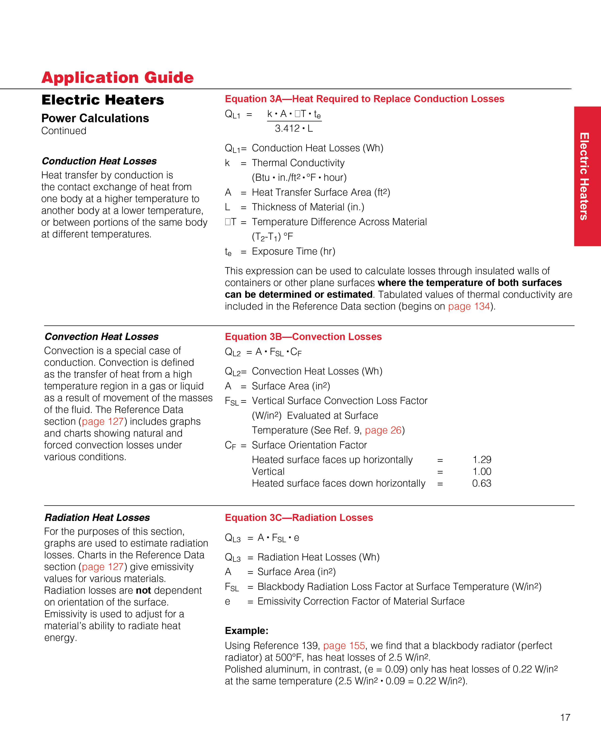
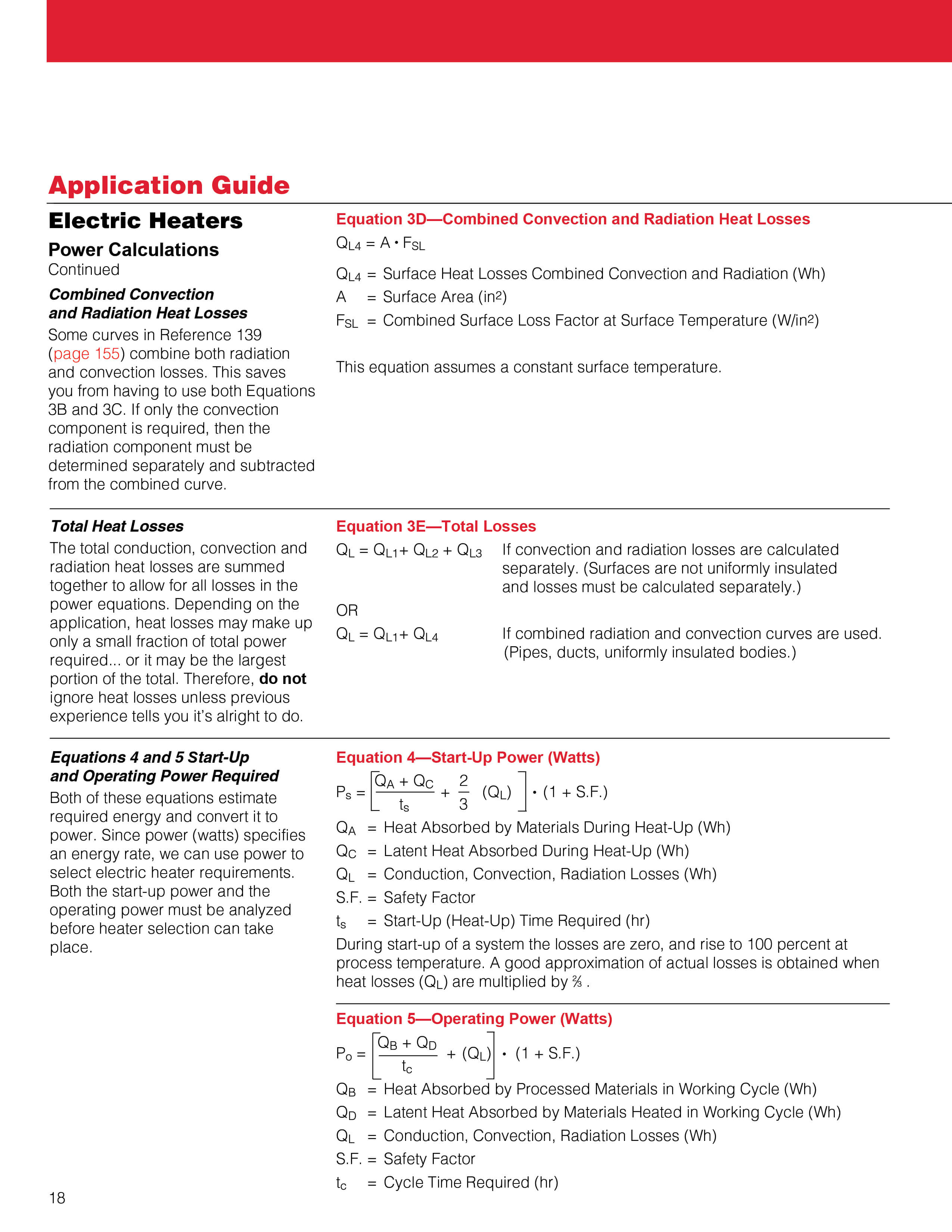
Following a few simple guidelines will not only reduce the likelihood of heater-related issues, but can actually have a significant positive impact on the efficiency of systems and reduce maintenance requirements and costs. Below are 10 ways to maximize a heater's service life and performance.Tip 1: Guard against heater contamination
Contamination is the most frequent cause of heater failure (see images). As heaters expand and contract during cycling, they often draw in organic or conductive materials. This can lead to an arcing failure between individual heater windings or between heater windings and the electrically grounded outer heater sheath. When allowed to collect at the lead end of a heater, contaminants can also cause electrical shorts between power pins or terminals. Therefore, it is important to keep lubricants, oils, low-temperature tapes or processing materials out of contact with the lead end of the heater. Employing seals will help.
Tip 2: Protect leads and terminations from high temperatures and excessive movement
Standard fiberglass-insulated lead wire may be used in applications with ambient temperatures up to approximately 260°C (500°F). If a lead is exposed to higher temperatures, high-temperature lead wire or ceramic bead insulation should be used. An unheated section of the heater, extending away from the heated region of the system, enables the leads to run at a beneficially cooler temperature. When heaters are mounted in moving machinery, it is essential to anchor the leads to prevent them from being damaged. A lead protection option should be specified and used for optimum protection against lead damage.
Tip 3: Heater selection and sizing are important
A heater's wattage should be matched as closely as possible to the application's actual load requirements to limit ON/OFF cycling (see tip 6). For fitted-part applications, specify the hole or an alternative application feature size to ensure an optimal fit between the heater and application feature. A tight fit minimizes air gaps and reduces the instances of hot spotting.
Tip 4: Ground the equipment
It is common sense and safe practice to electrically ground all equipment on which the heater is used. Grounding equipment helps protects plant and personnel in the event of an electrical failure in the heating system.
Tip 5: Regulating voltage ensures the rated heater voltage matches voltage supply
It is essential to ensure a heater's rated voltage matches the available voltage supply because wattage increases (or decreases) at the square of the change in voltage applied to a heater. For example, if a heater is rated for 120V/1000W and is connected to a 240V supply, it will generate four times the rated wattage output or 4000W. This will cause a heater to fail relatively quickly and can also cause significant damage the attached equipment.
Tip 6: Prevent excessive heater cycling
Excessive temperature cycling is very detrimental to the life of a heater. The most detrimental is the cycle rate that allows full expansion and contraction of the heater resistance wire at a high rate (30 to 60 seconds' power ON and power OFF). This causes severe stress and oxidation of the resistance wires inside a heater. A bad temperature cycle is typically found when thermostats are used. Thermostats respond slowly to temperature changes and have large switch ON/OFF temperature differentials. An improvement, but a somewhat more expensive solution, is to use ON/OFF or PID controllers with mechanical relays. It is crucial to not switch the frequency or cycle time too rapidly (somewhere between 3 to 10 seconds), because the relay contacts can wear out quickly.
The most effective way to minimize heater element temperature cycling, and the most expensive solution, is to use solid state relays (SSRs) and SCR power controllers coupled to PID temperature controllers. This combination provides the best performance for both your thermal system as well as for the heater itself. Solid state switching devices cycle power to the heater very rapidly (from one second with a SSR, down to milliseconds with phase-angle fired SCRs). This fast-power cycling dramatically reduces heater element wire temperature excursions and substantially extends heater life.
Tip 7: Ensure that the sheath material and watt density ratings are compatible with the material being heated
This is absolutely critical to ensure long heater life and healthy processing equipment. When heating solids, such as metals, the operating temperature and heater-to-part fit drive sheath material and watt density choices. Carbon steels, aluminum, silicone rubber sheath materials are fine for lower temperatures (a few hundred degrees). However, as temperatures increase beyond this point, sheath material choices become limited to galvanized or stainless steels and other higher temperature metal alloys. As temperature also increases, the watt density must decrease accordingly to prevent internal resistance wires from oxidizing quickly and failing prematurely. A good heater-to-part fit ensures proper heat transfer and does not force the resistance wires to overheat. When heating gases, the operating temperature and flow rates dictate what sheath material and watt density can be used. For example, you can run higher watt densities when heating hydrogen versus nitrogen, but hydrogen requires Alloy 800 sheaths, whereas 304 Stainless Steel will work for many nitrogen applications. Increasing flow and turbulence across the heater elements means better heat transfer, which raises watt density values. For liquid heating, the prime driver for materials and watt density selection is the fluid material and flow rate. Water can easily handle 42.52 to 70.87W/cm2 (60 to 100W/in2) using a copper sheath, whereas a 50/50-water/glycol mix can only handle 21.26 W/cm2 (30 W/in2) and must use a steel sheath.
Tip 8: Mount immersion tank heaters horizontally near the tank bottom
Heaters should be placed horizontally and near tank bottoms to maximize convective circulation. Vertical mounting is only advisable when limitations, such as space restrictions, prohibit horizontal placement. Regardless of whether a heater is mounted horizontally or vertically, it is essential to place it high enough to avoid any sludge and debris buildup in the bottom of the tank. Likewise, for both mounting methods, the entire heated length of the heater must be immersed at all times - one reason vertical mounting is rarely recommended. It is also important to avoid placing heaters in restricted spaces that limit convective flow and/or where free boiling or steam traps can occur.
Tip 9: Prevent build-up and sludge on the heater elements
Scale, coking and sludge build-up on heater sheaths must be minimized. Any accumulation should be periodically removed or at least minimized, to avoid inhibiting heat transfer to the liquid. Periodic cleaning prevents heater elements being forced to operate at higher temperatures, which can lead to early heater failure. Extreme care should also be taken to avoid getting silicone lubricant on the heated section of a heater. Silicone will prevent the "wetting" of the sheath by the liquid, act as an insulator, and possibly cause the heater to fail.
Tip 10: Ensure proper, tight temperature control and safety limit protection
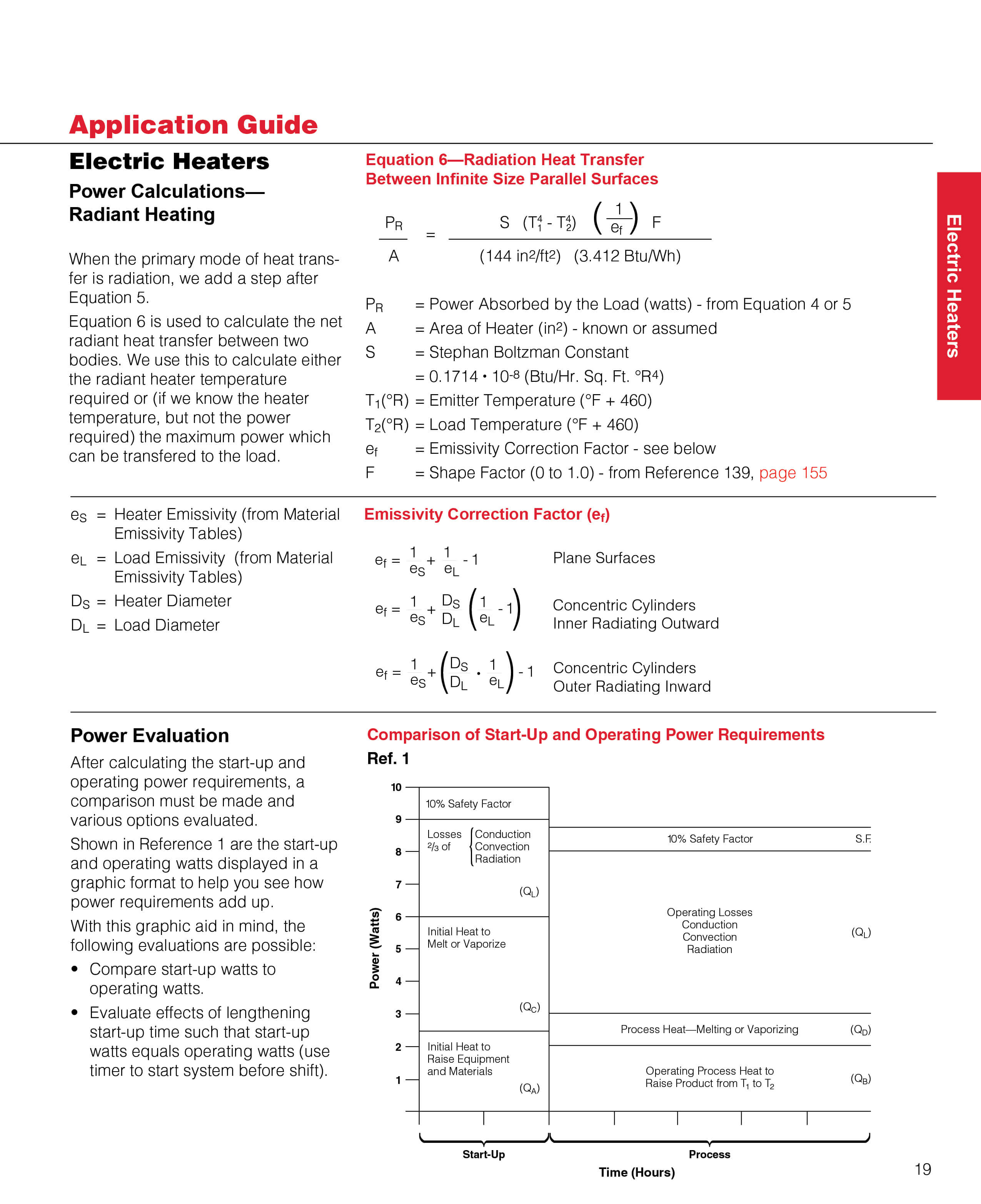
Matching the appropriate temperature control system to the heater is imperative to strong heater performance and life. Each process application should, at the very least, include a process temperature sensor (to sense the material being heated) and a limit sensor (to sense the heater sheath temperature). The process sensor should be directly immersed into the material to be heated, or snugly inserted into a thermowell inside the fluid itself. For safety reasons, two separate control systems should be used - one for process temperature control and one for high limit control. PID type process temperature controllers offer more stable control and faster. problem. Some of this supporting information may not be readily available or apparent to you. You may find it necessary to consult the reference tables and charts in this reference data section, or reference a book that deals with the particular parameter you need to define. At the minimum, the thermal properties of both the material(s) being processed/heated and their containing vessel(s) will be required. Figuring a safety factor requires some intuition on your part. The list of possible influences can be great. From changing ambient operating temperatures, caused by seasonal changes, to a change in material or material temperature being processed, you must carefully examine all the influences. Generally speaking, the smaller the system with fewer variables and outside influences---the smaller the safety factor. Conversely, the larger the system and the greater the variables and outside influences — the greater the safety factor.
Here are some general guidelines:
- 10% safety factor for small systems with closely calculated power requirements
- 20% safety factor is average20% to 35% for large systems
The safety factor should be higher for systems that have production operations that contain equipment cycles subjecting them to excessive heat dissipations, e.g.: opening doors on furnaces, introducing new batches of material that can be of varying temperatures, large radiant applications and the like.
-
8. Thermocouple Types
Thermocouple Type Useful/General Application Range Notes B 1370-1700°C (2500-3100°F) Easily contaminated, require protection. C* 1650-2315°C (3000-4200°F) No oxidation resistance. Vacuum, hydrogen or inert atmospheres. E** 95-760°C (200-1400°F) Reducing atmosphere recommended. Iron leg subject to oxidation a K** 95-1260°C (200-2300°F) Well suited for oxidizing atmospheres. N 870-1450°C (1600-2640°F) Oxidizing atmosphere recommended. Easily contaminated, require protection. S 980-1450°C (1800-2640°F) Laboratory standard, highly reproducible. Easily contaminated, require T** -200-350°C (-330-660°F) Most stable at cryogenic temperatures ranges. Excellent in oxidizing Type E
The Type E thermocouple is suitable for use at temperatures up to 900°C (1650°F) in a vacuum, inert, mildly oxidizing or reducing atmosphere. At cryogenic temperatures, the thermocouple is not subject to corrosion. This thermocouple has the highest EMF output per degree of all the commonly used thermocouples.
Type J
The Type J may be used, exposed or unexposed, where there is a deficiency of free oxygen. For cleanliness and longer life, a protecting tube is recommended. Since JP (iron) wire will oxidize rapidly at temperatures over 540°C (1000°F), it is recommended that larger gauge wires be used to compensate. Maximum recommended operating temperature is 760°C (1400°F).
Type K
Due to its reliability and accuracy, Type K is used extensively at temperatures up to 1260°C (2300°F). It's good practice to protect this type of thermocouple with a suitable metal or ceramic protecting tube, especially in reducing atmospheres. In oxidizing atmospheres, such as electric furnaces, tube protection is not always necessary when other conditions are suitable; however, it is recommended for cleanliness and general mechanical protection. Type K will generally outlast Type J because the JP (iron) wire rapidly oxidizes, especially at higher temperatures.
Type N
This nickel-based thermocouple alloy is used primarily at high temperatures up to 1260°C (2300°F). While not a direct replacement for Type K, Type N provides better resistance to oxidation at high temperatures and longer life in applications where sulfur is present.
Type T
This thermocouple can be used in either oxidizing or reducing atmospheres, though for longer life a protecting tube is recommended. Because of its stability at lower temperatures, this is a superior thermocouple for a wide variety of applications in low and cryogenic temperatures. It's recommended operating range is— -200° to 350°C (-330° to 660°F), but it can be used to -269°C (-452°F) (boiling helium).
Types S, R and B
Maximum recommended operating temperature for Type S or R is 1450°C (2640°F); Type B is recommended for use at as high as 1700°C (3100°F). These thermocouples are easily contaminated. Reducing atmospheres are particularly damaging to the calibration. Noble metal thermocouples should always be protected with a gas-tight ceramic tube, a secondary tube of alumina and a silicon carbide or metal outer tube as conditions require.
W-5 Percent Re/W-26 Percent Re (Type C*)
This refractory metal thermocouple may be used at temperatures up to 2315°C (4200°F). Because it has no resistance to oxidation, its use is restricted to vacuum, hydrogen or inert atmospheres.
*an ANSI symbol
**Also suitable for cryogenic applications from -200 to 0°C (-328 to 32°F)
-
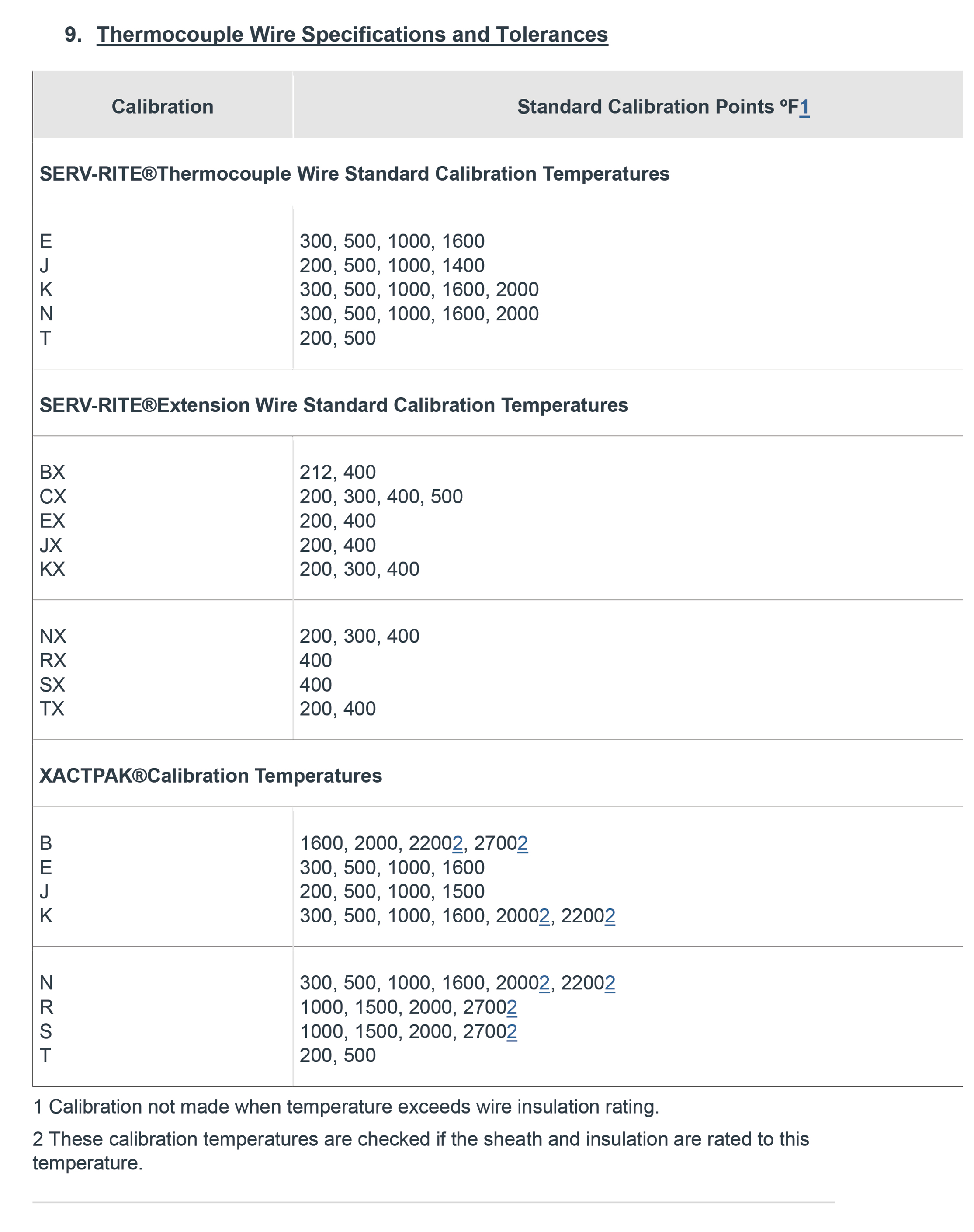
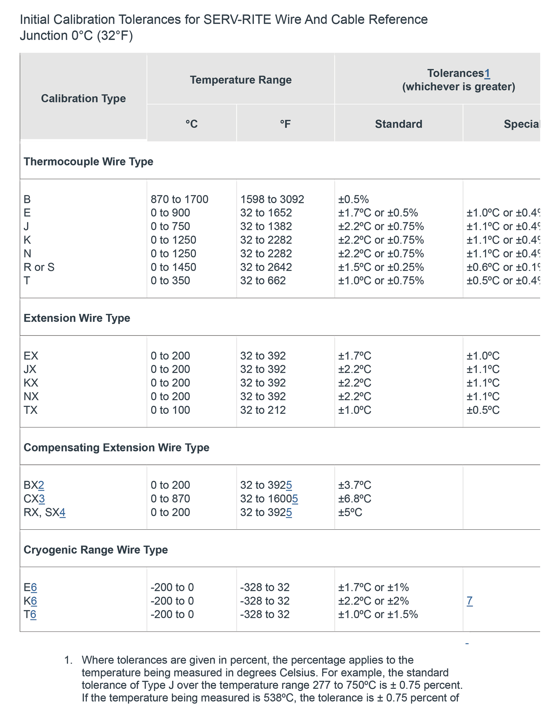
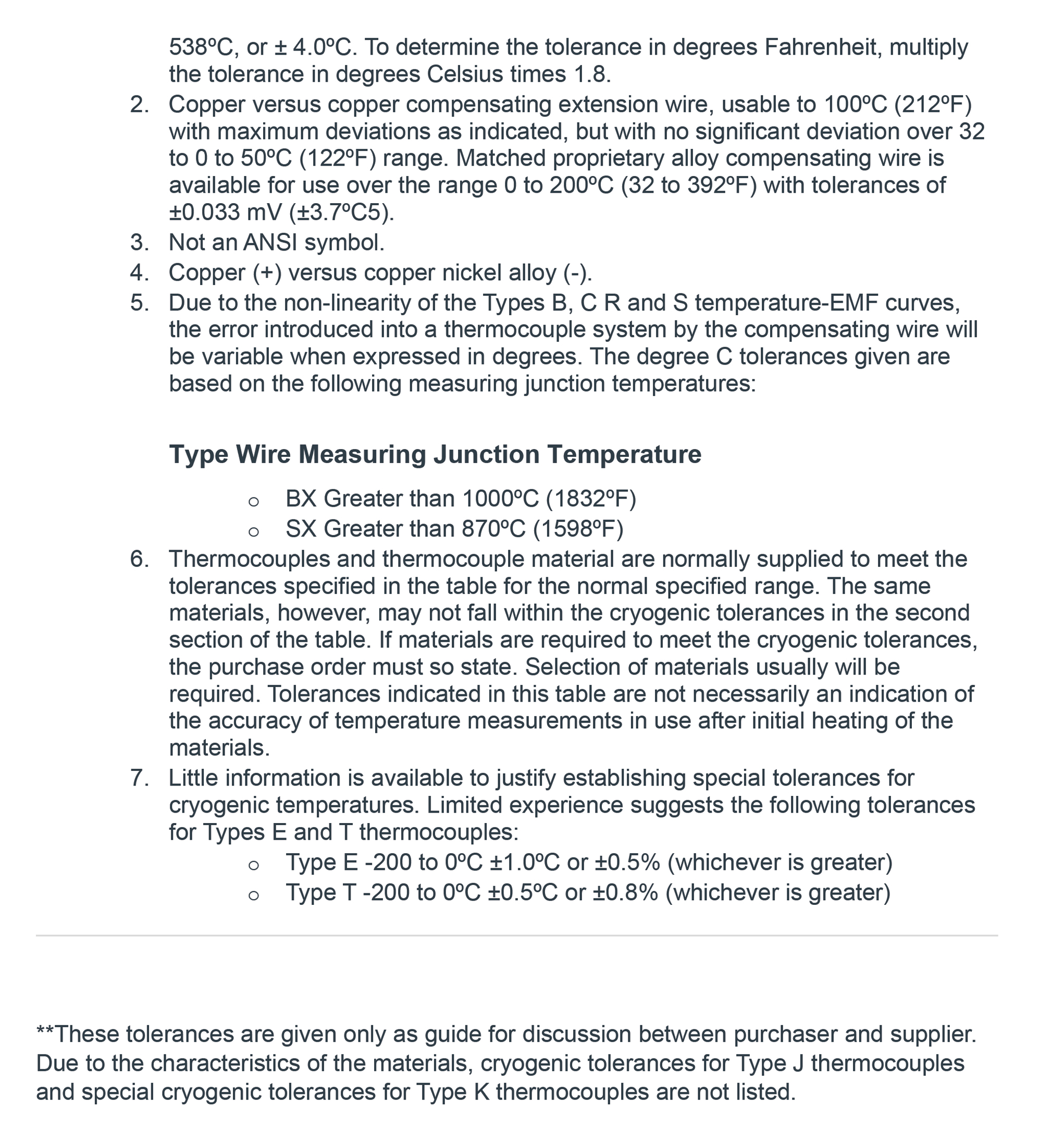
8. Thermocouple Wire Specifications and Tolerances
-
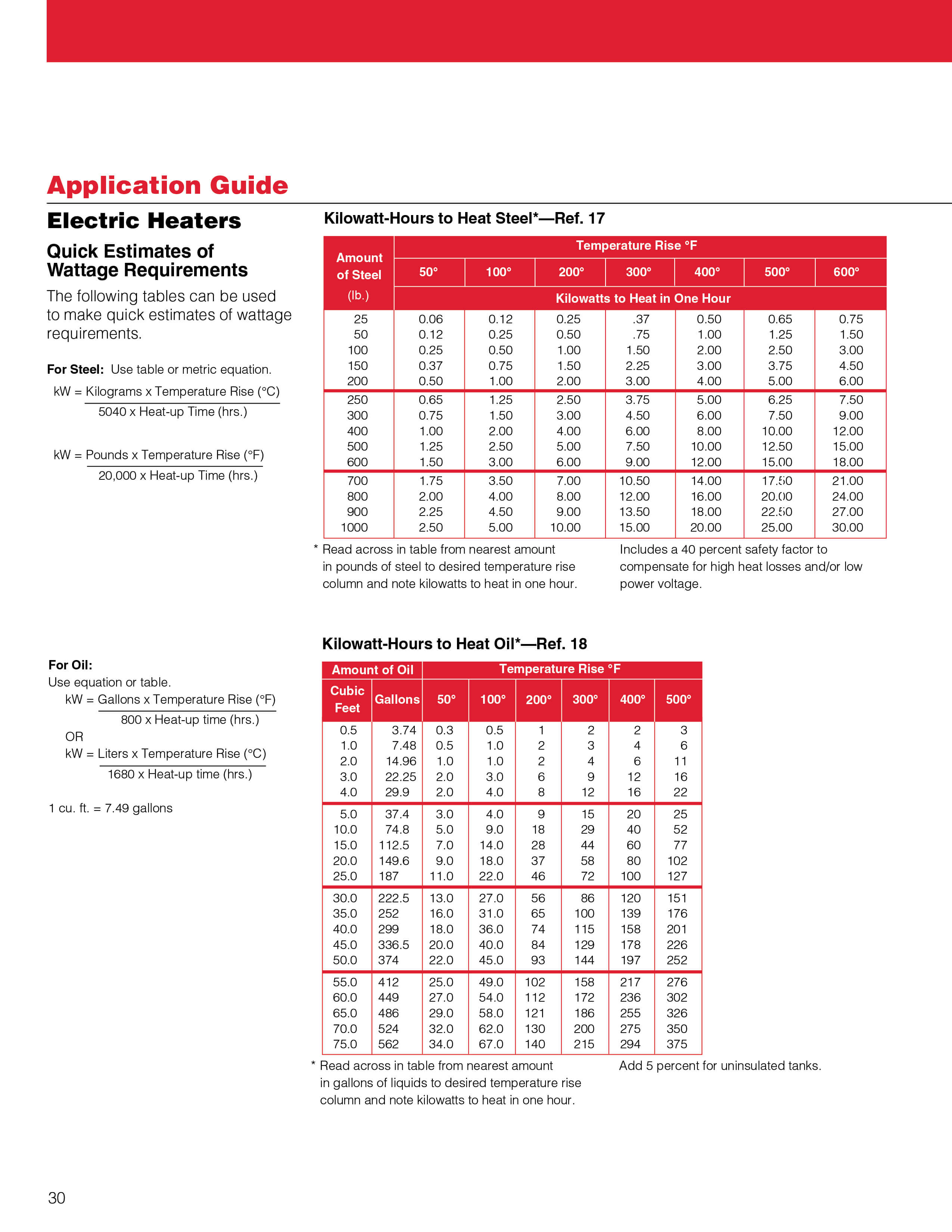
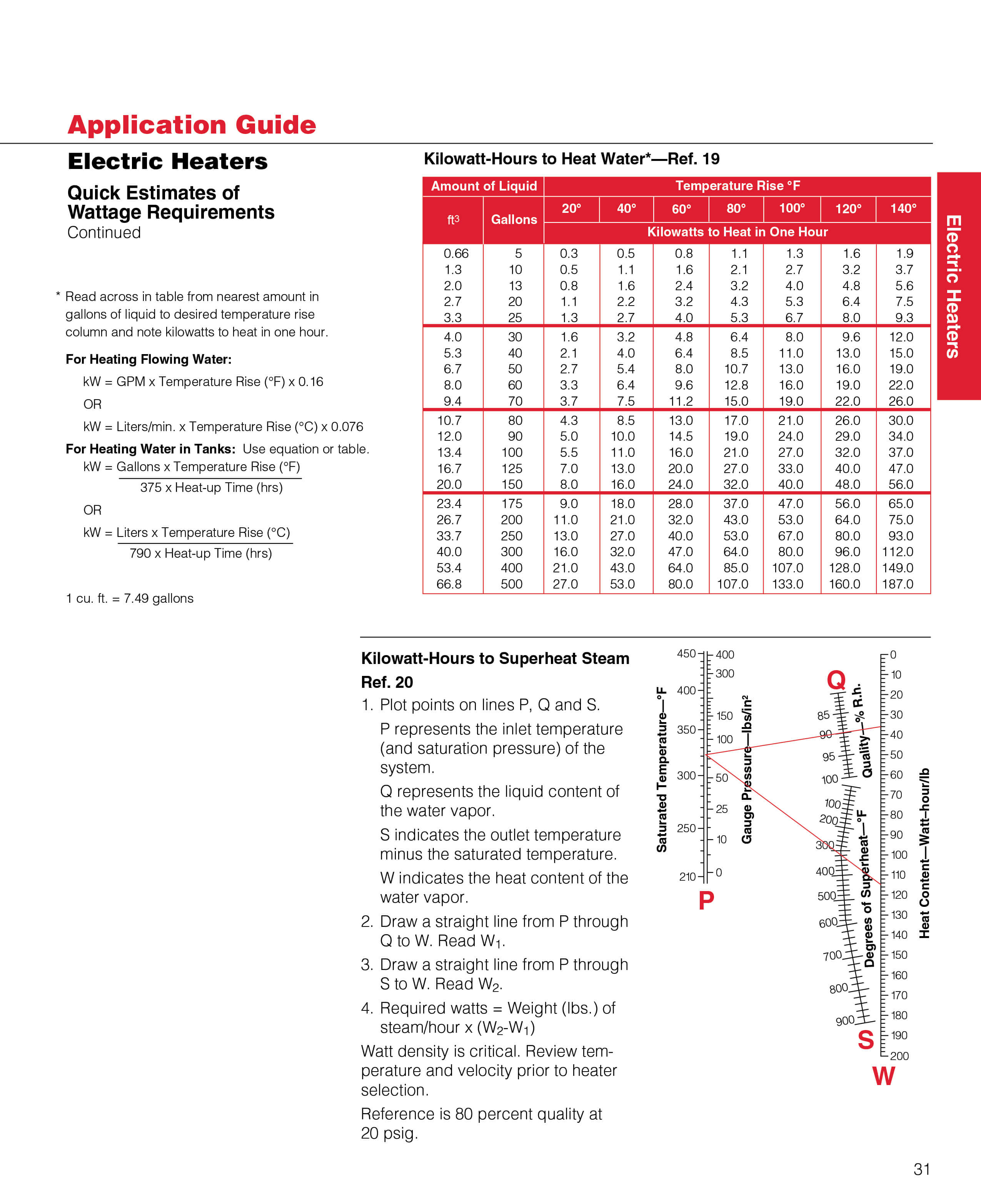
9.Wattage
-
10.Power Calculation